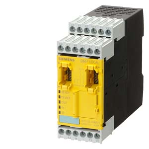
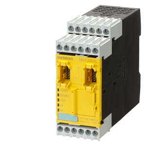
| | FAIL-SAFE DIGITAL MODULE DM-F LOCAL; FOR FAIL-SAFE SWITCH-OFF VIA HARDWARE SIGNAL; UV: 110...240 V AC/DC, 2 RELAY ENABLING CIRCUITS; 2 RELAY OUTPUTS; SAFETY FUNCTION CAN BE SELECTED VIA DIL SWITCH; MAX. ERR. SIL (IEC 61508): 3; MAX. ERR. PL (ISO 13849-1): E; |
| |
| General technical data: |
| product brand name | | SIRIUS |
| Item designation / according to DIN EN 61346-2 | | F |
| Item designation / according to DIN 40719 extendable after IEC 204-2 / according to IEC 750 | | KT |
| |
| Installation/mounting/dimensions: |
| Built in orientation | | any |
| Type of mounting | | screw and snap-on mounting |
| Width | mm | 45 |
| Height | mm | 106 |
| Depth | mm | 124 |
| |
| Connections: |
| Design of the electrical connection / for auxiliary and control current circuit | | screw-type terminals |
| Conductor cross-section that can be connected / for auxiliary contact | | |
| | mm² | 0.5… 4 |
| | | |
- with conductor end processing
| mm² | 0.5… 2.5 |
| |
| Ambient conditions: |
| Ambient temperature | | |
| | °C | -25… +60 |
| | °C | -40… +80 |
| | °C | -40… +80 |
| Relative humidity | | |
| | % | 5… 95 |
| Installation altitude / at a height over sea level / maximum | m | 2,000 |
| Protection class IP | | IP20 |
| Resistance against vibration | | 1-6 Hz / 15 mm; 6-500 Hz / 2 g |
| EMC immunity to interference / according to IEC 60947-1 | | corresponds to degree of severity 3 |
| Conductor-bound parasitic coupling BURST | | |
- according to IEC 61000-4-4
| | 2 kV network connection / 1 kV control connection |
| Conductor-bound parasitic coupling conductor-earth SURGE | | |
- according to IEC 61000-4-5
| | 2 kV |
| Conductor-bound parasitic coupling conductor-conductor SURGE | | |
- according to IEC 61000-4-5
| | 1 kV |
| Field-bound parasitic coupling | | |
- according to IEC 61000-4-3
| | 10 V/m |
| EMC emitted interference / according to IEC 60947-1 | | class A |
| Insulation voltage / rated value | V | 300 |
| Impulse voltage resistance / rated value | V | 4,000 |
| |
| Safety: |
| safety Integrated Level / according to IEC 61508 | | SIL3 |
| Performance level (PL) / according to ISO 13849-1 | | e |
| Category / according to EN 954-1 | | 4 |
| Category / according to ISO 13849-1 | | 4 |
| Product function | | |
| | | Yes |
| | | Yes |
| | | Yes |
| | | Yes |
- protective door monitoring
| | Yes |
- magnetic switch monitoring Normally closed contact-Normally open contact
| | Yes |
| | | Yes |
- magnetic switch monitoring Normally closed contact-Normally closed contact
| | Yes |
| | | Yes |
| Acceptability for application | | |
- EMERGENCY-OFF circuit monitoring
| | Yes |
| | | Yes |
- position switch monitoring
| | Yes |
| | | Yes |
- magnetically operated switches monitoring
| | Yes |
- proximity switches monitoring
| | No |
- tactile sensor monitoring
| | No |
- opto-electronical protection device monitoring
| | Yes |
| | | No |
| Product feature / transverse contact-secure | | Yes |
| Design of the input / start-up entrance | | Yes |
| Design of the input / reducing-entrance | | Yes |
| Design of the cascading | | cascading |
| Design of the input / cascading-entrance/operation-even switching | | Yes |
| Probability of dangerous failure per hour (PFHD) / with high demand rate / according to EN 62061 | 1/h | 0.458E-8 |
| Average probability of failure on demand (PFDavg) / with low demand rate / according to IEC 61508 | 1/y | 0.548E-5 |
| SIL claim limit (for a subsystem) / according to EN 62061 | | 3 |
| T1 value / for proof test interval or service life / according to IEC 61508 | a | 20 |
| Make time | | |
| | | |
| | ms | 50 |
| | ms | 100 |
| | ms | 100 |
| | | |
| | ms | 8,000 |
| | ms | 8,200 |
| | | |
| | ms | 50 |
| | ms | 100 |
| Backslide delay time / after opening of the safety circuits / typical | ms |
|


